Phew, never again am I hand building more than one board this complex!
I have been away on holiday at Glastonbury music festival, and then to recover from that I had another two weeks away. Now I am back, and apart from some contract work to finish (which pays for this project) I have more free time to work on the bring up. Several boards are out at developers and they are making good progress. I am working on the boot software and the FPGA wrapper which handles all the board IO, like PS2, memory controller etc. The idea is to make it easy for anyone to drop a “core” into the wrapper and not worry about the interfaces – you can think of it as an SDK for the board.
I have just got a small TV I can dedicate to this, so the current focus is to bring up the video and audio outputs, and finish testing the on board memory.
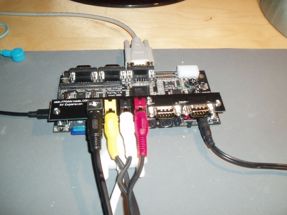
Picture above shows the board cabled up and connected to the digital TV.
I’m using a LG M227WD screen as it’s small, cheap, true 1080 display and has all the video inputs I need including S-Video, composite, scart and HDMI/DVI. The bottom cable is a DVI to HDMI cable. HDMI is backwards compatible with DVI so you just need a cable with the right ends on. The advantage of using HDMI over DVI is that the screen will work at 50Hz PAL resolutions, which is what we need.
Replay board with the optional AV expansion card. The AV card provides PAL & NTSC S-Video and composite video with luma trap for the best possible quality output. I forgot to order the board spacers so the bolts are holding the two cards together for now. It is more robust that it looks!
Back of the IO board. Not too interesting.
This is the LCD panel. This is really just for fun and this expansion board is not intended for production (although I have a few of them). It is to test the 800×480 touchscreen and drivers so I can make a true portable if there is demand. Analog joystick not arrived yet.
The back of it. The wire is needed as I can’t fit the front connector as the LCD connector gets in the way. I added the flexy cable in the CAD system, turned off the drawing layer and forgot about it. Luckily the components there are low enough the cable goes over them ok, and it was only 5V power which was taken from the small connector.
Here is the board in it’s development mode with the 68030 expansion board.
 Just to give you an idea how small this thing is, here is a soft drink tin to give you scale – other brands available – although free samples always appreciated 🙂
The board fits in mini-atx or itx case, and I may need to as the cables pull the board around. I am going to stick it to the desk to stop it escaping.
Right, enough chat, I’ll get on with the testing.


